What to know
EXOR HMIs are equipped with serial ports that can be managed by internal controller CODESYS V2 or V3
The sample project attached is made to show the concept of use receiving strings terminated by CR/LF and re-send it out.
What to do with CODESYS V2 iPLC on eTOP500/600
The "CODESYS v2 Target Support Package for eTOP500/600" provides specific function blocks to manage serial ports and send/receive characters through them. These funcion blocks are included inside "EXOR_Serial.lib" library.
To insert this library inside a CODESYS V2 project:
1. Open project resources and double-click on Library Manager:
2. Select Insert > Additional Library...
3. Browse for Lib_EXOR subfoder
4. and select Exor_Serial.lib
The library contains the following function blocks:
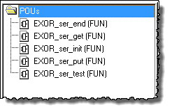
EXOR_ser_init function block is the first to be used to initialize the serial port with the desired communication parameters.
These parameters must be defined before to open a serial connection with panel an external device:
- port :
For eTOP400 series 1 = COM1 (PLC port), 2 = COM2 (PC/printer port).
For eTOP500/600 series1 = COM1 (PLC port), 2 = COM2 (Optional 232/485 module mounted on Slot#1 or #2),
3 = COM3 (Optional 232/485 module mounted on Slot#3 or #4) - channel : default value is 0 = PLC Port, 1 = PC/Printer port
- baudrate : allowed values 2400, 4800, 9600, 19200, 38400, 57600, 115200, 230400
- parity : type of parity control are 0 = disabled, 1 = even, 2 = odd
- data format : default value is 8; number of data bits supported are: 7 or 8
- stop bit : default value is 1; no other value are admitted in this case.
- mode : default value is FALSE; mode of operation for driver (only for external
channel): False = RS232, True= RS485 - halfduplex : defualt value is FALSE; when true, the RTS signal is driven to enable
the serial driver
during transmission received chars are disregarded - slewrate : default value FALSE; slew rate of the driver (only for external channel):
False = FAST True= SLOW.
In attachment you can find the sample project "SerialPortExample_CDS2_eTOP.zip".
This application listen chars coming on serial interface till CR/LF then write out buffered chars like an echo.
What to do with CODESYS V2 iPLC on SCMxx Modules
The "CODESYS v2 Target Support Package for SCM03C/05C/11C/12C" provides specific function blocks to manage serial ports and send/receive characters through them. These funcion blocks are included inside "EXOR_Serial.lib" library.
Installation of this library is the same as per above.
EXOR_ser_init function block is the first to be used to initialize the serial port with the desired communication parameters.
These parameters must be defined before to open a serial connection with panel an external device:
- port :
For SCM03 modules we only have available one serial port and this has to set to "0"
For SCM05/11/12 we have 2 serial ports (on the module) and this parameter can be set to "1" or "2". Using serial port 1 you loose the Workbench connection; note that serial port refers actually to the UART; the channel parameter is then used to "connect" the UART to a physical connector - channel : default value is 0 = PLC Port or COM1, 1 = PC/Printer port or COM2
- baudrate : allowed values 2400, 4800, 9600, 19200, 38400, 57600, 115200, 230400
- parity : type of parity control are 0 = disabled, 1 = even, 2 = odd
- data format : default value is 8; number of data bits supported are: 7 or 8
- stop bit : default value is 1; no other value are admitted in this case.
- mode : default value is FALSE; mode of operation for driver (only for external channel): False = RS232, True= RS485
- halfduplex : default value is FALSE; when true, the RTS signal is driven to enable the serial driver during transmission received chars are disregarded
- slewrate : default value FALSE; slew rate of the driver (only for external channel): False = FAST True= SLOW.
In attachment you can find the sample project "SerialPortExample_CDS2_SCM.zip".
This application listen chars coming on serial interface till CR/LF then write out buffered chars like an echo.
What to do with CODESYS V3 iPLC on eTOP500/600
CODESYS v3 workbench include itself needed library to access eTOP500/600 serial ports.
To include this library inside a CODESYS V3 project do the following:
- Open project tree and double-click on Library Manager
- Click on "Add library" button
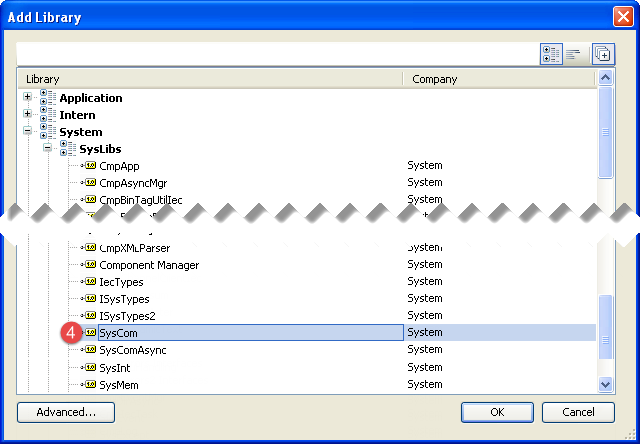
3. Into "Add Library" dialog, select [+] to display advanced library:
4. Then browse for System > SysLibs > SysCom, and confirm with OK:
Result will be:
Refer to the example project "SerialPortExample_CDS3_eTOP_V2.zip" attached for library usage.
This application listen chars coming on serial interface till CR/LF then write out buffered chars like an echo.
Appendix: Debug using PC
To test projects in attachment we suggest to connect a PC with serial interface to the HMI running CODESYS application via RS-232 link.
On PC can be used a terminal emulator like HyperTerminal or TeraTerm.
Proper cable to connect to SCM03/05/11/12 modules plugged on UniOP Legacy series is:
CA002 - UniOP Programming Port to AT RS-232 (DTE DE9S)
Proper cable to connect to eTOP500/600 series is:
CA253 - UniOP eTOP300/400/500 Serie Serial Port to AT RS-232 (DTE DE9S)
Attachments
SerialPortExample_CDS3_eTOP_V2.zip


